Monday, October 28, 2013

November 5:

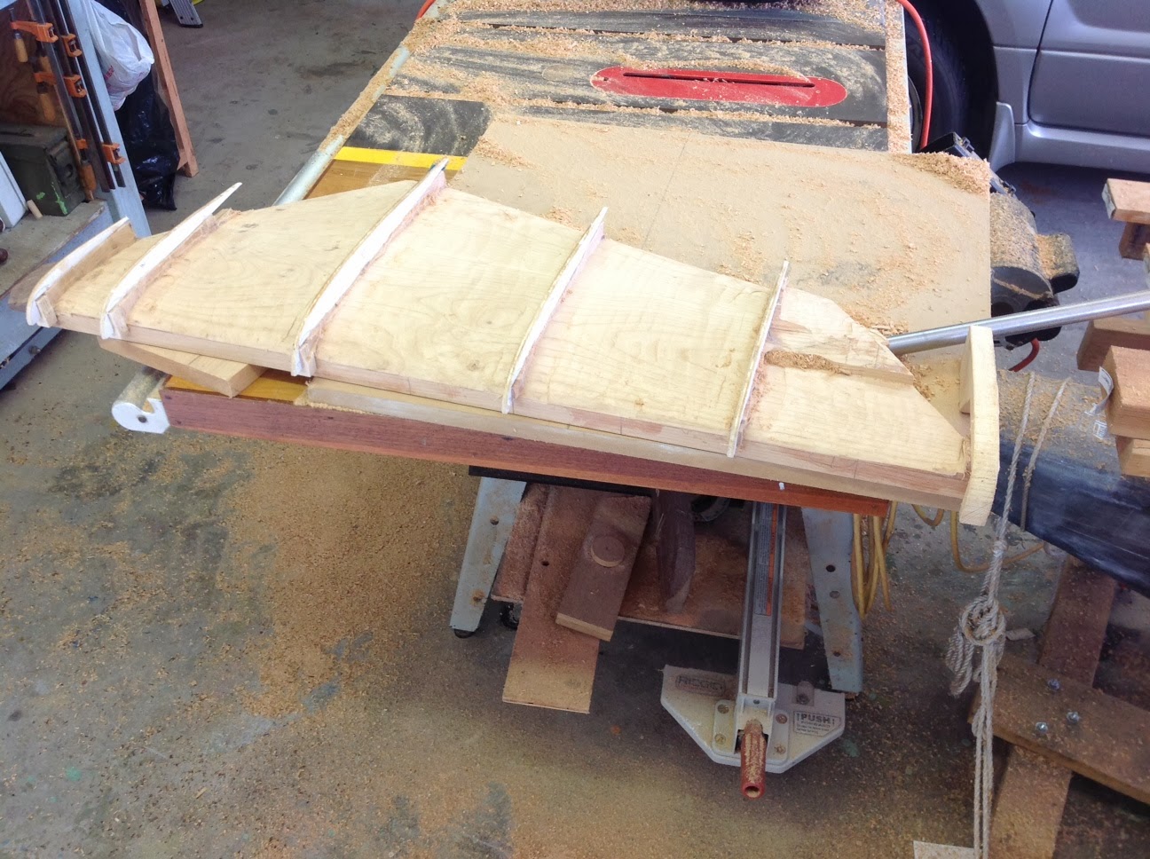
The router bit slipped a bit last week so adding more material at trailing edge.  Should be able to glass the entire profile by this weekend.


October 30:


The rudder is developing.  It took some time to layout and decide what balance could be achieved while housing the stock and keeping an angle similar to what is used with modern FFs.
Goal:
1. 15-30% balance by area.
2. Rudder stock angle from vertical 6-30 degree.
3.  Rudder center of pressure centered on stock (by area).
Final:  15.4%, 14 degree from vertical, centered by area

The 97/2 plan profile of the rudder shows the airfoil normal to the leading edge of the rudder which is 43 degrees from vertical.  The first method was to stack the profiles with wood blocks and shape it down to the profiles.  I started with a naca 0011 foil which closely matches the plan profile but in the orientation this would develop an ambiguous profile wrt. to actual water flow.  Re-mapping the profile in the direction of flow then plotting the resultant points for a 'normal to leading edge' orientation gave a new profile matched to another naca profile.  Oversize patterns were cut and will be used to rough in the shape with a router suspended across the profiles.  Next step is finish internal shaft and torque pin assembly followed with epoxy glue up of ll parts.

A first layer of epoxy was used on the keel after giving it a better support rack.  Bad news is the keel has a 25 mm twist in it placing the end point of the fin off center laterally.  Will compensate with some shaping and the final mounting hole pattern to backbone.


Sunday, September 22, 2013

Keel weighing and drilling

Keel flange is now drilled.  Easy job except the slow steps of positioning the keel safely.  Need to research the method of sealing it with epoxy or paint or whatever.  I imagine epoxy with thickener, sanded out and covered with paint?  Comments any one?  Bolt pattern will have 10x 3/8 bolts.


Made a mistake with the keel right out.  I forgot to add a hole in the base to tune the weight in the future. I wish I had a Carlton drill press now.  But I checked the weight with a lever assembly and two counter loads and averaged 390 lbs. (6.1: 181+/-12 kg, 373 lbs - 425 lbs) so all is well.  

I next moved the keel and hoisted it adjacent to the work bench to gain a good position for drilling.  I would like to finish the keel up to some decent point after which it can store for the future.  I will lay it beneath the base framing that is half built.  Time to figure bolt patterns and sizes.


Sunday, September 15, 2013

Rudder and Base


September 25th:
In the last few days I put up the base and developed a rudder plan.  Small and large project work will proceed in parallel so that at night I can make progress without waking the dogs around the neighborhood. The RUDDER should qualify as quiet work.  The design is to take the provided cross section from plan 97/2 of the ruder and scale it within the fore/aft profile.  As the profiles approach the hull they will gradually angle until parallel with the edge adjacent to the hull.

Compared to old pictures of F15s being built circa 1940s it appears I have a relatively stout BASE to setup the station moulds.  I am leaning towards laminating a backbone over the moulds but that could be troublesome with a 4ft wide base.  Only half of the base is setup at this point and I am using it is as a table for laying out the stations profile.  The plans are curious enough with some variations between the loft table and full size station dimensions.  I don't suppose I will ever get this boat class approved but the aim would be strict adherence to the rules.  I will use two layers of 1/8 marine ply formed primarily over a set of stringers on the moulds.  Frames will be laminated and placed densely in high stress area of keel and less so along boat length.  It is not determined yet if steam bent or laminated frames will be used.  The fine frame arrangement on classics as shown in the photo below does not apply.  A recent ffblog page indicated that was the method used prior to epoxies and a large number of small bronze nails visible on the outer surface were driven through each frame.  Also stringers built into the hull are not currently considered, just a laminated frame network and bulkhead panels to carry the load path out from the core to the hull, shrouds, etc.


Thursday, September 5, 2013

Keel

The keel arrived and was trucked over from Kona side.  Funny that the location in Hilo is where I stopped by to ask about free pallets to use in mold making.  Well there they are, one stop shopping!!
Lessons learned (not my favorite phrase):
1.  Get advice on shipping.  I saved 300-600 bucks by following suggestions.
2.  Keel does not need a pretty box to get home.  The pallet here was provided by Commercial.
3.  Getting those holes on the flange..well there is a machine shop down the street from the shipper or I rig up the press at home...hmmmm lesson to be learned soon.
4.  Glad I waited on project till this arrived, it was touch and go for awhile.

Wednesday, July 17, 2013

Shipping costs!!

A rough week with a good ending.  I checked a previous quote for shipping the keel to Hawaii and the cost went up 3x.  I almost keeled over.  I checked further with other carriers and it only got worse.  With prices in the $600.00 range I settled myself by thinking that this is what they charge to ship me to Hawaii and I am self loading.  Things changed with some helpful input from a friend and I am going to ship the mold in a cardboard box, well wrapped.  The casting house said that is fine and that they can strap the finished piece to a pallet and send it off.  A quote for the return pallet came in at $250.00 so the show is on!   If anyone needs a really nice crate for storing a Flying Fifteen keel I have got a deal for you. 

Sunday, June 30, 2013

California or Bust!

Finally ready to ship the keel plug to California for casting.  Plan is ship this to the casting house then have keel returned with plug lying on top in this crate.  There is just a bit of extra room.  I suppose someone in the future may need to make one of these so here it will rest for future generations/regattas.  Crate is reinforced across the bottom with oak strips to support 370lb load about its C.G.  Next stop:  California or Bust!

Tuesday, May 28, 2013

Time to start glassing the form.  I probably do not need to do that for a one time use form but I am looking for some practice before taking on the rudder job.