
Log of the construction of a Flying Fifteen keelboat in Hilo, Hawaii
Tuesday, May 6, 2014

Tuesday, February 18, 2014
More of the same. Lots of scarf and glue. The glue bench could use an upgrade but so far everything is straight. Maybe two weeks before a real layup is possible. It would be nice to do A-E sections. I revised the laminate sheet and I am considering steaming the length of the laminates from the stem to section 3 then drying them in the form jig. The 10 mm sections take the curve but one cracked at section 2. With six or seven layers I dont want to blow it up.


Saturday, February 1, 2014
Had some difficulty with resawing and controlling board shape. It is getting better but going real slow. There is a warp in the plank I started with that I am fighting that has forced some an extra step of building up planks for the lamination layers. Each piece is getting a coat of epoxy following the West System folks method. Some wood bees have really been storming the jig as well. Three of them just today. The ants are in the process of carrying away their bodies.
The scarf tool, resaw jig, and epoxy coating work space are setup so as soon as the design gets adjusted for these errors in sizing it should pick up speed. Well we'll see.


The scarf tool, resaw jig, and epoxy coating work space are setup so as soon as the design gets adjusted for these errors in sizing it should pick up speed. Well we'll see.
Monday, December 9, 2013


All forms are now cut and aligned. A recheck of profile points are within 3mm.

Stations 8, 7, 6 and the transom points do not create a fare line. Does anyone know if this is normal for F15 hulls? I discovered the comment section is not working and so a message to wymanrt@yahoo.com would be great. I imagine I will redo this section with a batten and miss the loft points by several mm. The form is almost ready for lamination work.
The first marking of center-line points measured from the baseline shows they are skewed. Will have to reset sections of form and remark or rotate baseline reference.

Stations 8, 7, 6 and the transom points do not create a fare line. Does anyone know if this is normal for F15 hulls? I discovered the comment section is not working and so a message to wymanrt@yahoo.com would be great. I imagine I will redo this section with a batten and miss the loft points by several mm. The form is almost ready for lamination work.
The first marking of center-line points measured from the baseline shows they are skewed. Will have to reset sections of form and remark or rotate baseline reference.


Moving along I decided to construct the backbone stand alone in the upright or flat orientation (TBD) then build the stations and insert it within them. The cross members will be added after the initial lamination and shaping and finally trimmed within the shell fairing. Building base is coming along. The backbone went through several revisions to where finally the cross pieces (frames and buttresses) are moved to the top of the lamination stack instead of in the middle making the work easier. A 10 mm cap will sandwich both assemblies. A few more days of vacation should get the lamination started.


Backbone construction: Planning to work with African Mahogany for majority of backbone along with Oak for frames and ? for buttresses at four points in the area of the keel flange. Two frames will be fore and aft of keel centroid longitudinally and one set will terminate near the shroud attachments. The basic layout still being refined is shown below. Stiffness of stern area up to rudder attachment is being studied with shell and panels. Load distribution out from keel attachment along with other stress points; mast, shrouds, jib, etc. will tweak the design before any molds can be setup.

Finished parts waiting for a home. Still work to do here but at a good stopping point until the hull forms.


Friday, November 8, 2013
If anyone has suggestions on paint I could use some input. I do not see the need for special anti-fouling or metal paints since it will not stay in the water for more than a day. Here is my list so far:
I ran out of epoxy but it is all ready for glass and fairing. After that I will give it a coat of paint and store it. Perhaps some more tuning on the keel to clean up the first two layers and prep for storing. Then the real work gets started, building the back bone and stations but design is still progressing. I probably will not have any posts for quite awhile. And it will be time to pay the English for the building right.
- Pettit Unepoxy
- Pettit easypoxy
- Pettit Shipendec Enamel Paint
- Rustoleum Oil based enamel
- Krylon spray enamel
Any comments?, Thanks.
---------------------------------


Monday, October 28, 2013
November 5:
The router bit slipped a bit last week so adding more material at trailing edge. Should be able to glass the entire profile by this weekend.

October 30:


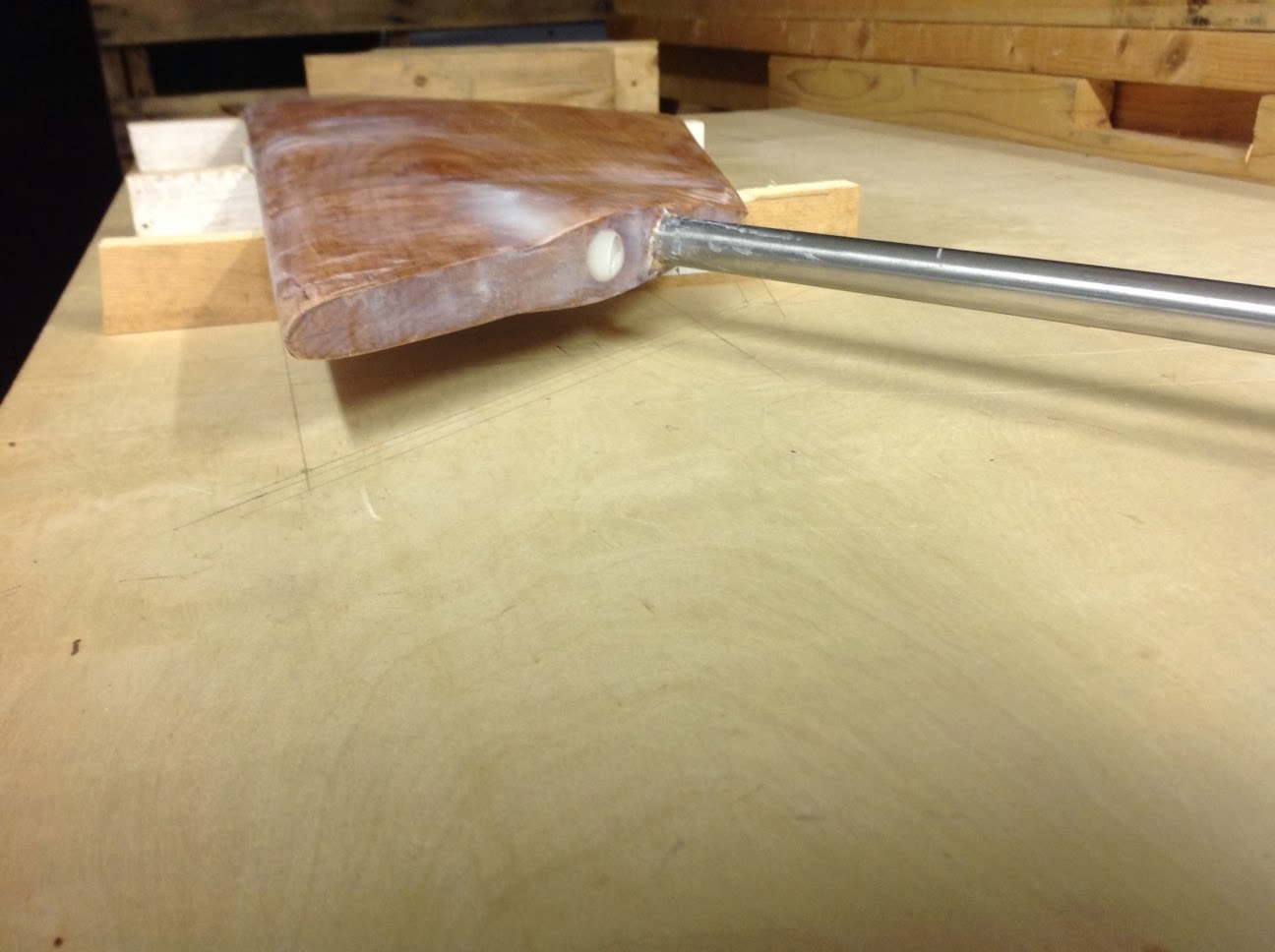
The rudder is developing. It took some time to layout and decide what balance could be achieved while housing the stock and keeping an angle similar to what is used with modern FFs.
Goal:
1. 15-30% balance by area.
2. Rudder stock angle from vertical 6-30 degree.
3. Rudder center of pressure centered on stock (by area).
Final: 15.4%, 14 degree from vertical, centered by area
The 97/2 plan profile of the rudder shows the airfoil normal to the leading edge of the rudder which is 43 degrees from vertical. The first method was to stack the profiles with wood blocks and shape it down to the profiles. I started with a naca 0011 foil which closely matches the plan profile but in the orientation this would develop an ambiguous profile wrt. to actual water flow. Re-mapping the profile in the direction of flow then plotting the resultant points for a 'normal to leading edge' orientation gave a new profile matched to another naca profile. Oversize patterns were cut and will be used to rough in the shape with a router suspended across the profiles. Next step is finish internal shaft and torque pin assembly followed with epoxy glue up of ll parts.
A first layer of epoxy was used on the keel after giving it a better support rack. Bad news is the keel has a 25 mm twist in it placing the end point of the fin off center laterally. Will compensate with some shaping and the final mounting hole pattern to backbone.


The router bit slipped a bit last week so adding more material at trailing edge. Should be able to glass the entire profile by this weekend.

October 30:


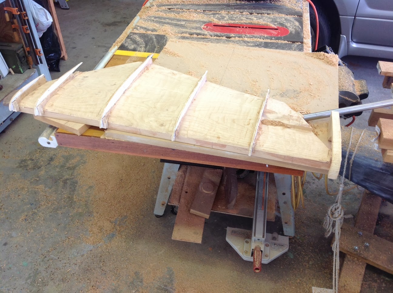


The rudder is developing. It took some time to layout and decide what balance could be achieved while housing the stock and keeping an angle similar to what is used with modern FFs.
Goal:
1. 15-30% balance by area.
2. Rudder stock angle from vertical 6-30 degree.
3. Rudder center of pressure centered on stock (by area).
Final: 15.4%, 14 degree from vertical, centered by area
The 97/2 plan profile of the rudder shows the airfoil normal to the leading edge of the rudder which is 43 degrees from vertical. The first method was to stack the profiles with wood blocks and shape it down to the profiles. I started with a naca 0011 foil which closely matches the plan profile but in the orientation this would develop an ambiguous profile wrt. to actual water flow. Re-mapping the profile in the direction of flow then plotting the resultant points for a 'normal to leading edge' orientation gave a new profile matched to another naca profile. Oversize patterns were cut and will be used to rough in the shape with a router suspended across the profiles. Next step is finish internal shaft and torque pin assembly followed with epoxy glue up of ll parts.
A first layer of epoxy was used on the keel after giving it a better support rack. Bad news is the keel has a 25 mm twist in it placing the end point of the fin off center laterally. Will compensate with some shaping and the final mounting hole pattern to backbone.


Sunday, September 22, 2013
Keel weighing and drilling

I next moved the keel and hoisted it adjacent to the work bench to gain a good position for drilling. I would like to finish the keel up to some decent point after which it can store for the future. I will lay it beneath the base framing that is half built. Time to figure bolt patterns and sizes.
.JPG)
.JPG)
Subscribe to:
Posts (Atom)