Sunday, March 29, 2015

  1. Finish cold molding --- complete 4-7-15
  2. Install 5 mm offset Douglas fir strip to front leading edge of hull.
  3. Rough sand and check loft values.
  4. Final staple check and rough epoxy fill of surface damage.
  5. Scrape hull, sand hull all over.
  6. Apply epoxy + Q cell and fare hull all over.
  7. Sand faring layer.
  8. Apply 10 oz e-glass layer all over. 
  9. Cleanup and sand if needed.
  10. Apply carbon fiber fabric in aft regions, 2 x 6' x 2'.
  11. Cleanup and sand if needed.
  12. Apply epoxy + Q cell and fare hull all over.
  13. 1st orbital sand faring layer.
  14. Apply epoxy + Q cell and fare hull all over.
  15. 2nd orbital sand faring layer or board sand all over.
  16. Align and pre-drill rudder stock port.
  17. Apply epoxy primer coating. 
  18. Cut brad nail attachment of hull to mold.  
  19. Lift hull and flip over.  Remove mold assembly and install upright supports.  Install hull on base and supports.  Following these steps the external surface will be left unpainted and the hull flipped over to begin internal structure work.  
 Add 5 mm trim along front edge where offset was made.  I will check the loft values after this cures then shape it.
Last staple :)


Upcoming steps to get the hull ready for internal work is as follows:
    Just about there...and another gallon of resin bites the dust!


Saturday, March 14, 2015

It is finally official the boat has IFF sail number 4034.  Hope to float this before 5000 comes along.  Cold mold layer is at 75% completion level.  Working on a tiller design after being inspired by this post:  https://flyingfifteen.wordpress.com/2015/03/13/flying-fifteen-carbonology/


Wednesday, March 4, 2015

Laminating has been on hold a few days while some storms come through.  High humidity makes for uncertain work.  Decided to test the laminate structure for refining hull design interior which seems to be quickly upon us. 

A test is performed to measure elastic modulus of hull laminate with respect to orientation angle in order to aid in identifying internal stringer alignment positions and spacing. The stringers are in excess of existing design bulkheads and frames which concentrate on rig and deck support and load transfer from keelson to shell in high stress points of keel mount. Attention to large flat areas in bow and after of keel on hull bottom are under special attention.

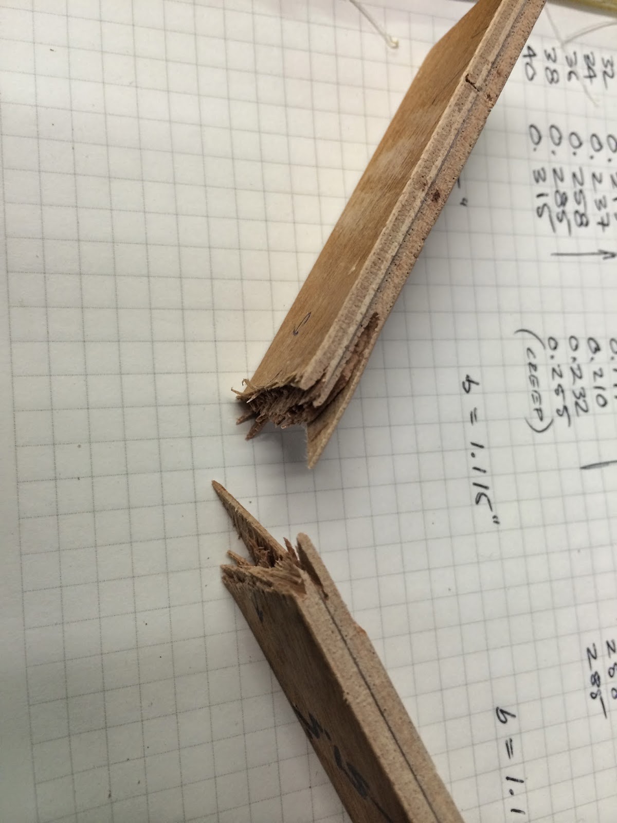
Measurements are made on samples of laminate structure that are cut from a hull sample that matches actual. No attempt was made to further refine the laminate structure beyond two 3mm marine ply sheets constructed of 3 each plys having 0/90/0 orientation. The orientation angle is measured from the horizontal baseline set to 0 degree with the boat upside down. Two samples are aligned with the cold molded strips at 53.5 degree and 128.5 degree. Strips are approximately 28.5mm x 3mm cross section and 133mm between supports on a loading apparatus. The loader applies a force to the middle of the sample suspended on simple supports. Deflection is measured at the center and loading is up to 50lbf. Two samples were made at each angle of 0, 90, 53.5, 128.5 deg. Unfortunately samples were not prepared for 128 deg to 180 deg. A plot of orientation vs modulus is made for 360 degrees and averages E for each common pair.  Samples I and J exhibited a run away creep at full test load and were allowed to go to failure. 
Results as follows prior to refining data and modifying hull construction design elements.


Sample OrientationE
#anglepsiMpa
A 90 606,918 4185
B 90 535,913 3695
C 0 609,315 4201
D 0 582,125 4014
E 22.5 577,332 3981
F 67.5 400,534 2762
G 53.5 350,833 2419
H 53.5 365,887 2523
I 128.5 465,069 3207
J


128.5


469,235


3235


Test setup, indicator, sample loader, scale and jack.